
JRG/JT™ Models ML · MLE · SG · HG
Jet Pumps for Gas Applications
Versatile, no-moving-parts solutions for gas exhausting, tank evacuation, vacuum service, and priming. Operate with liquid, steam, or compressed air as the motive medium. Available ½″–12″ in 316SS, carbon steel, bronze, and PVC.
Overview
There are two major types of applications using eductors to pump gases: exhausting and evacuation. JRG/JT eductor models for liquids pumping gases are ML and MLE; for gases pumping gases: SG and HG. All four models can be used for both exhausting and evacuation.
Most JRG/JT eductors are available in sizes from ½″ through 3″ in a wide variety of materials. Units are available in sizes up to 12″. In some cases, specialty eductors can pump a suction volume up to 50 times the motive volume. Expedited deliveries are available when needed.
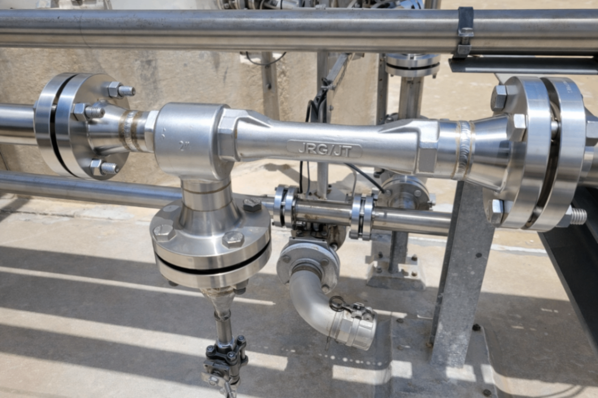
JRG/JT™ shown in 316LSS
Operating Specifications
| Parameter | ML | MLE | SG | HG |
|---|---|---|---|---|
| Motive Media | Liquid | Liquid | Steam, Air | Steam, Air |
| Motive Pressure (PSIG) | 20–250 | 20–250 | 60–120 | 20–80 |
| Max. Vacuum (in Hg) | 29 | 29 | 24 | 24 |
| Outlet Pressure (PSIG) | 20 | 20 | 12 | 20 |
| Applications | Exhaust / Evacuate / Prime | Exhaust / Evacuate / Prime | Exhaust / Evacuate / Prime | Exhaust / Evacuate / Prime |
Typical Applications by Motive Fluid
| Application | Liquid Motive ML, MLE | Steam Motive SG, HG | Air / Gas Motive SG, HG |
|---|---|---|---|
| Vacuum Filtration | ✓ | ✓ | ✓ |
| Exhaust Vessels | ✓ | ✓ | ✓ |
| Evacuate Vessels | ✓ | ✓ | ✓ |
| Aerate Liquids | ✓ | — | — |
| Distillation | ✓ | ✓ | ✓ |
| Prime Pumps | ✓ | ✓ | ✓ |
Application Types
Exhausting — Continuous Gas Removal
Exhausting involves removing gases at a continuous rate from an area while maintaining the pressure at a stable level. These applications often involve removing gases or fumes that are continuously recurring — for example, removing smoke from a welding or machining area. This process can also be used for injecting oxygen into a liquid stream. If the gases being removed have undesirable characteristics, it is possible in some cases to neutralize them by using a reactive motive fluid.
Units are sized based on a desired flow rate of gas through the eductor (SCFM or Lb/Hr).
Evacuation — Pressure Reduction in a Defined Volume
Evacuation involves pulling gases from a defined volume by pumping the tank down from a starting pressure to a final lower pressure. It is generally sized by determining the amount of time it takes to reduce the pressure in the vessel to the desired final pressure. Examples include reducing the pressure in a reaction vessel to purge it of detrimental gases, or removing steam from a vessel before opening it to increase operator safety.
A variation is using eductors to prime piping or a system with liquid — bringing liquid up to pump level to avoid a dry start or to establish a siphon. Rule of thumb: priming takes approximately twice as long as an equivalent evacuation.
Principles of Operation
Eductors operate on the basic principles of flow dynamics. A high-pressure motive stream is accelerated through a tapered nozzle to increase the velocity of the fluid. Gas motives are compressible fluids and are put through a converging-diverging nozzle — the gas can exceed the speed of sound. This high-velocity fluid then passes into a secondary chamber where friction between its molecules and those of the suction gas causes the secondary gas to be pumped. Both fluids mix intimately and are discharged from the eductor.

Three Connections Common to All Eductors
Where the power for the eductor is generated by increasing the velocity of the motive fluid. Eductors with liquid motives use a converging nozzle, as liquids are not generally compressible. Eductors with gas motives utilize converging-diverging nozzles to achieve maximum benefit from the compressibility of the gas. All JRG/JT nozzles have smooth flow paths — rough surfaces cause eductors to operate less efficiently.
Where the pumping action takes place. The motive fluid passes through the suction chamber, entraining the suction gas as it passes. Friction between the fluids at their interface evacuates the chamber, allowing pressure in the suction vessel to push additional flow into the suction connection. The high velocity of the motive stream directs the combined fluid toward the discharge section.
As the motive fluid entrains the suction gas, part of its kinetic energy is imparted to the suction gas. This allows the resulting mixture to discharge at an intermediate pressure. The percentage of motive pressure recovered is dependent upon the ratio of motive flow to suction flow and the amount of vacuum at the suction connection.
Model Selection Guide
Best when water supply is available. MLE and ML capacities are often close — size both to find the optimal unit. When using liquids to pump gases, the eductor acts as a volume-displacing device; gas weight has only minimal effect on performance.
Generally used with higher-pressure motive flows. Can pull a deeper vacuum and is typically the more efficient choice when motive pressure is available in the 60–120 PSIG range.
Designed for lower motive pressures. Higher motive flow rate; can discharge against higher outlet pressures. Use when motive supply is limited to 20–80 PSIG.
How to Size for Exhausting Gases
Exhausting is a continuous operation. Units are sized based on a desired flow rate of gas (SCFM or Lb/Hr) through the eductor.
Convert all pressures and flows to the units used in the sizing table (PSIG, in Hg, SCFM, GPM). If you regularly size in other units, request a special sizing table from your representative.
Find the value equal to or greater than your system back pressure in the Outlet Pressure (Po) column. Use that section of the table for all subsequent steps.
Find the row equal to or higher than your desired suction pressure. If the pressure falls between two table values, interpolate or use the lower value for a conservative estimate.
In the Ps row, find the column where motive pressure equals your operating condition. Interpolate if needed, or use the lower value for a conservative estimate.
Divide your desired suction flow (Qs) by the tabulated flow for each model. This gives the required S.F. Select the next standard size with an S.F. equal to or larger than calculated. The model with the larger suction capacity is generally the more efficient unit.
Multiply the tabulated motive flow (Qm, GPM) by the selected S.F. to get the actual water consumption.
Worked Example — Liquid Motive (ML/MLE)
| Parameter | Value |
|---|---|
| Desired suction flow (Qs) | 5 Lb/Hr air |
| Desired suction pressure (Ps) | 5 in Hg Vac |
| Motive water pressure (Pm) | 40 PSIG |
| Outlet pressure (Po) | 11 ft head |
| Conversions | 5 Lb/Hr × 13.35 ft³/Lb ÷ 60 = 1.1 SCFM air 5 in Hg Vac → 29.92 − 5 = 24.92 in Hg Abs 11 ft ÷ 2.31 = 4.8 PSIG |
| Result | Select 1″ MLE (S.F. ≈ 0.34), requiring ~8.2 GPM water |
Sizing SG & HG Models (Gas/Steam Motive)
The procedure is identical to the liquid-motive steps above, using the SG/HG exhausting tables. Key guidance:
- Prefer SG when motive pressure is 60–120 PSIG — it is generally the more efficient unit.
- HG is used when motive pressure is limited to 20–80 PSIG or when higher outlet pressure capability is needed.
- Example: 17 SCFM at 7 in Hg Vac, 80 PSIG steam, 5 PSIG outlet → SG 1-¼″ or 1″ depending on exact table values.
How to Size for Evacuating Gases
The ML/MLE and SG/HG evacuation charts give the time in minutes to evacuate 1 ft³ to the listed pressure from atmospheric pressure. Sized at atmospheric outlet; higher outlet pressures up to the lesser of 5% of motive pressure or 5 PSIG are generally acceptable.
Convert all pressures and volumes to the units used in the table.
Desired Time per ft³ = Desired evacuation time ÷ Volume (ft³) to be evacuated.
Find the column matching your motive pressure (Pm).
In the Ps row for your final suction pressure, read the time per ft³ for the 1-½″ standard unit.
Choose an S.F. such that (tabulated time ÷ S.F.) ≤ desired time per ft³.
Actual time = Volume (ft³) × (tabulated time per ft³ ÷ S.F.). Motive water = tabulated Qm × S.F.
Worked Example — Liquid Motive Evacuation
45 ft³ vessel, target 4 minutes, 60 PSIG motive, final pressure 10 in Hg Abs →
Select 2″ MLE, actual time ≈ 3.47 min, motive water ≈ 47.7 GPM.
Worked Example — Steam Motive Evacuation
35 ft³ vessel, 12 minutes to 15 in Hg Abs, 60 PSIG steam →
Select SG ½″, actual time ≈ 3.5 min, steam ≈ 26.6 Lb/Hr.
Sizing Factors (S.F.) — All Models
Performance tables are based on the 1-½″ standard unit. Multiply tabulated flows by the S.F. for your pipe size.
| Unit Size | ½" | ¾" | 1" | 1-¼" | 1-½" | 2" | 2-½" | 3" | 4" | 6" | 8" | 10" | 12" |
|---|---|---|---|---|---|---|---|---|---|---|---|---|---|
| S.F. | 0.12 | 0.21 | 0.34 | 0.61 | 1 | 1.82 | 3.17 | 5.92 | 11.8 | 24 | 49 | 71 | 123 |
The 1-½″ unit is the standard reference (S.F. = 1.00). Applies to ML, MLE, SG, and HG models.
Correcting for Different Gases — Dry Air Equivalent (DAE)
Performance data is based on air at 70°F. Use the Dry Air Equivalent (DAE) method (per Heat Exchange Institute Standards for Steam Jet Vacuum Systems) to correct for other gases and temperatures.
Convert all component flows to Lb/Hr.
Calculate the average molecular weight of the non-condensable gases.
Obtain the Molecular Weight Entrainment Ratio and Temperature Entrainment Ratio from the tables below.
Apply the correction formula to obtain total DAE (Lb/Hr). Use this value as Qs when sizing.
Temperature Entrainment Ratio
| Gas | 100°F | 200°F | 300°F | 400°F | 500°F | 600°F | 700°F | 800°F | 900°F | 1000°F |
|---|---|---|---|---|---|---|---|---|---|---|
| Steam | 0.992 | 0.958 | 0.925 | 0.892 | 0.86 | 0.818 | 0.792 | 0.76 | 0.728 | 0.692 |
| Air | 0.994 | 0.97 | 0.945 | 0.923 | 0.898 | 0.874 | 0.85 | 0.825 | 0.803 | 0.778 |
Molecular Weight Entrainment Ratio
| MW | 10 | 20 | 30 | 40 | 50 | 60 | 70 | 80 | 90 | 100 | 110 | 120 | 130 | 140 |
|---|---|---|---|---|---|---|---|---|---|---|---|---|---|---|
| Ratio | 0.58 | 0.85 | 1.02 | 1.14 | 1.23 | 1.32 | 1.38 | 1.43 | 1.46 | 1.49 | 1.52 | 1.55 | 1.57 | 1.6 |
Molecular Weights of Common Gases
| Gas | Formula | Molecular Weight |
|---|---|---|
| Ammonia | NH₃ | 17.03 |
| Benzene | C₆H₆ | 78.12 |
| Carbon Dioxide | CO₂ | 43.999 |
| Carbon Monoxide | CO | 28.01 |
| Chlorine | Cl₂ | 70.906 |
| Ethane | C₂H₆ | 30.07 |
| Hydrogen | H₂ | 2.016 |
| Methane | CH₄ | 16.043 |
| Oxygen | O₂ | 31.998 |
| Sulfur Dioxide | SO₂ | 64.058 |
| Water | H₂O | 18.015 |
Assembly Dimensions — Models ML, MLE, SG, HG
All dimensions in inches (mm). Standard connections are female NPT. Optional connections — Socket Weld, Victaulic, Silbraze, Sch 80 Butt Weld, 150# Flange — will increase dimensions A, B, and/or C; consult factory.
| Size | A | B | C | D | E (Motive) | F (Suction) | G (Gauge) |
|---|---|---|---|---|---|---|---|
| ½" | 4.500 (114) | 1.625 (41) | 1.250 (32) | ⅜ (10) | ½ (15) | ½ (15) | ⅛ (3) |
| ¾" | 5.875 (149) | 2.000 (51) | 1.500 (38) | ½ (15) | ¾ (20) | ¾ (20) | ¼ (7) |
| 1" | 7.125 (181) | 2.250 (57) | 1.750 (44) | ¾ (20) | 1 (25) | 1 (25) | ¼ (7) |
| 1-¼" | 9.000 (229) | 2.500 (64) | 2.250 (57) | 1 (25) | 1-¼ (32) | 1-¼ (32) | ¼ (7) |
| 1-½" | 11.000 (279) | 2.750 (70) | 2.500 (64) | 1 (25) | 1-½ (40) | 1-½ (40) | — |
| 2" | 14.375 (365) | 3.125 (79) | 3.000 (76) | 1-¼ (32) | 2 (50) | 2 (50) | — |
| 2-½" | 18.125 (460) | 3.500 (89) | 4.125 (105) | 1-½ (40) | 2-½ (65) | 2-½ (65) | — |
| 3" | 23.875 (606) | 4.000 (102) | 5.000 (127) | 2 (50) | 3 (80) | 3 (80) | — |
Dimension G (optional gauge port) applies to ½″–1-¼″ sizes only. Contact factory for sizes above 3″ or for fabricated construction.
Product Features
- No moving parts — zero maintenance, long service life
- Improved suction flow and discharge pressure capabilities
- Cost-effective solution for general vacuum service
- Vacuum levels down to 5 in Hg Absolute with steam or air motive
- Available with investment cast body for complex geometries
- 316 stainless steel standard with NPT connections
- Special sizes available with fabricated construction
- PVC construction available for corrosive service
- Expedited delivery available
- Sizes ½″–12″; standard stock ½″–3″
Large Inventory
- Jet Pumps in stock ½″–3″ in Carbon Steel, 316SS & Bronze
- Tank Eductors stocked ⅜″–3″ in Carbon Steel & 316SS
- PPL & PVDF Tank Eductors stocked ¼″, ⅜″, ¾″, 1″ & 1½″ MNPT
Quick Reference
Related Pages
Need a Sizing?
Fill out our jet pump application sheet and we'll reply with the recommended model, price, and availability.
Jet Pump Application FormTry the Sizing CalculatorYou Might Also Need
Related Products
Liquid Jet Pumps
Pump, transfer, or lift liquids. Carbon Steel, 316SS, Bronze. In stock ½″–3″.
Steam Jet Heaters
Inline direct-contact heating. Models 301, 320 & 340. No moving parts.
Tank Mixing Eductors
Full-tank mixing without agitators. Carbon Steel, 316SS, Hastelloy. In stock ⅜″–3″.
What's Next?
Continue Your Research
Sizing Calculator
Estimate flow rates and motive requirements for your application.
Product Selector Wizard
Answer 3 questions and get an instant product recommendation.
Request a Quote
Submit your process conditions and we'll size and price it for you.
Prefer to talk it through? Call 1+201-419-6111