
Eductors for Pumping Liquids
Jet pumps — also known as eductors or Venturi pumps — are highly reliable fluid-handling devices with no moving parts. Ideal for condensate recovery, sump drainage, tank transfer, and liquid pumping in demanding industrial environments.
Understanding Jet Pumps: Advantages and Applications
Jet pumps, also known as eductors and Venturi pumps, are highly reliable fluid-handling devices that leverage principles of fluid dynamics to pump, mix, or transport liquids, gases, and solids. These devices operate without any moving parts, making them exceptionally durable, low-maintenance, and well-suited for demanding industrial environments.
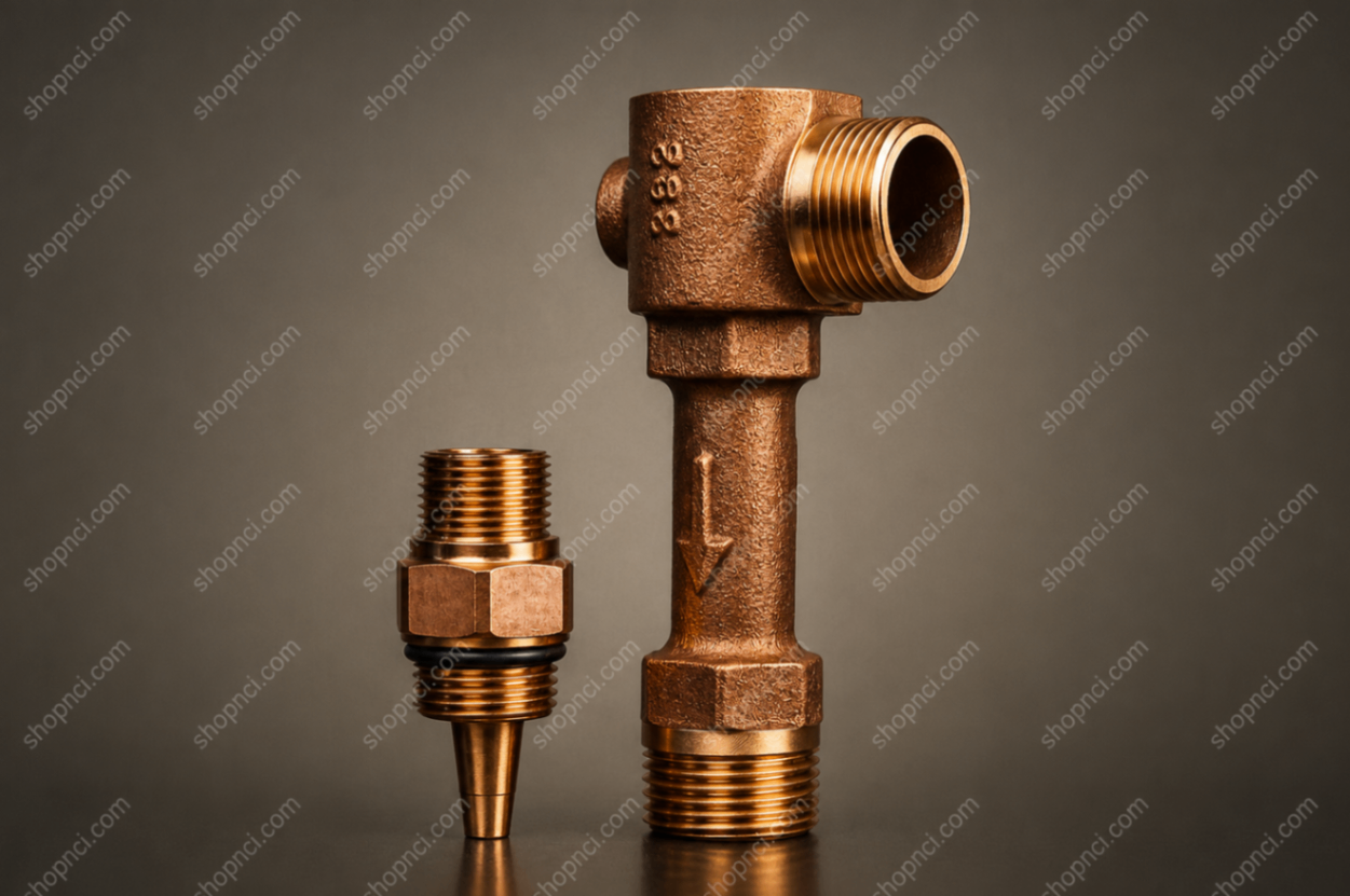
Principles of Operation
Eductors operate on the basic principles of flow dynamics. A high-pressure motive stream is accelerated through a tapered nozzle, increasing the velocity of the fluid. This high-velocity jet passes through a suction chamber where friction between the motive molecules and the secondary (suction) fluid causes the suction fluid to be entrained and pumped. The two fluids are intimately mixed and discharged from the eductor at an intermediate pressure.
Eductors with liquid motives use a converging nozzle — liquids are not generally compressible. All JRG/JT nozzles feature smooth internal flow paths; sudden steps or surface roughness on these high-velocity surfaces cause eductors to operate less efficiently.
Where the power for the eductor is generated by increasing the velocity of the motive fluid. The converging nozzle takes advantage of the physical properties of the liquid motive.
Where the pumping action takes place. The motive fluid passes through the suction chamber, entraining the suction fluid. The high velocity directs the combined fluids toward the outlet.
Part of the kinetic energy of the motive fluid is imparted to the suction fluid, allowing the mixture to discharge at an intermediate pressure through the diverging taper.

Key Advantages
- No moving parts — Resulting in exceptional reliability, negligible wear, and minimal maintenance requirements.
- Simple, compact design — For straightforward installation and long operational life.
- Versatile material options — Including corrosion-resistant constructions suitable for aggressive chemicals or harsh conditions.
- Broad applicability — Across liquid, gas, or multiphase (including solids) handling scenarios.
Typical Applications
Achieving homogeneous blends of fluids or creating uniform slurries with suspended solids.
Transferring liquids between tanks, vessels, or pipelines, especially where conventional pumps face challenges.
Conveying granular materials like sand, gravel, or catalyst particles in a liquid carrier stream.
Producing suction for tank evacuation, degassing, priming, or process venting.
Industry-Specific Uses
| Industry | Common Applications |
|---|---|
| Water & Wastewater Treatment | Chemical dosing, tank mixing, sludge circulation, fluid transfer |
| Oil & Gas | Chemical injection into drilling fluids, produced water handling, blending |
| Mining | Reagent mixing in slurries, solids transport, sump dewatering |
| Food & Beverage | Sanitary blending of ingredients, CIP fluid circulation |
| Chemical Processing | Safe handling and mixing of corrosive, reactive, or hazardous fluids |
Performance Considerations
Performance depends on motive pressure, suction conditions, discharge head, and fluid properties. For liquid motive applications, operating pressures range from 15–250 PSIG. The correct unit is always the one that matches your desired range of motive-to-suction flows most closely.
The percentage of motive pressure that can be recovered depends on the ratio of motive flow to suction flow and the amount of suction pressure pulled on the suction port. The mixture passes through a diverging taper that converts kinetic energy back to pressure before leaving the outlet.
Model Series — Operating Specifications
Based on pumping water at 68°F. Liquid motive models (SL, ML, HL) operate at 15–250 PSIG; steam motive models (SG, HG) use steam at 30–150 PSIG.
| Model | Motive Media | Motive Pressure (PSIG) | Pressure Recovery % | Max Suction Lift | Min NPSH | Best For |
|---|---|---|---|---|---|---|
| SL | Liquid | 15–250 | 10–15% | 27 ft | 3 ft | High suction flow, low discharge head |
| ML | Liquid | 15–250 | 30–35% | 27 ft | 3 ft | Balanced pumping — medium head |
| HL | Liquid | 15–250 | 40–50% | 27 ft | 3 ft | High discharge head; dilution applications |
| SG | Steam | 30–150 | 15–20% | 20 ft | 13 ft | Steam motive — standard pressure recovery |
| HG | Steam | 20–150 | 30–35% | 20 ft | 13 ft | Steam motive — higher pressure recovery |
HL = highest pressure recovery; best for dilution (throttle suction port). SL = highest suction flow ratio. SG/HG use steam as motive — no water supply needed.
Typical Applications by Motive Fluid
| Application | Liquid Motive SL, ML, HL | Steam Motive SG, HG, TLM521 |
|---|---|---|
| Pump from Tank | ✓ | ✓ |
| Pump from Sump | ✓ | ✓ |
| Dilute in Line | ✓ | — |
| Transport Liquid | ✓ | — |
| Heat Liquid | — | ✓ |
| Prime Pumps | — | ✓ |
| Evacuate Liquid Lines | — | ✓ |
How to Select the Right Eductor — 5-Step Method
All JRG/JT performance tables use the 1½″ unit as the standard. Eductors are sized using a Sizing Factor (S.F.) based on this standard unit.
Locate the suction lift equal to or greater than your desired lift. If your lift falls between two table values, use an average. For greater accuracy, use the NPSH formula — it corrects for temperature variations and friction losses.
Locate the outlet head equal to or greater than your actual outlet head. Include friction losses in the desired outlet head. Calculate friction losses using the combined rate of both motive and suction flows. The outlet line should be as large as or larger than the outlet connection.
Locate the motive pressure closest to or lower than your actual motive pressure. Calculate the Desired Sizing Factor: S.F. = Desired Suction Flow ÷ Tabulated Suction Flow. Do this for each model (SL, ML, HL).
Multiply the Qm and Qs values from the tables by the Tabulated S.F. obtained in Step 3. Do this for each model.
Choose the unit that best meets your motive and suction parameters. If a turndown ratio greater than 35% is needed, use two or more eductors in parallel. For pumping applications, maximize suction flow while minimizing motive consumption. For dilution, maximize motive flow and throttle the suction port.
Performance Data & Sizing Factors
The tables below give suction flow Qs (GPM) for the 1‑1/2″ standard unit across all motive pressures and suction/outlet head combinations. Use the Sizing Factor table to scale results to any pipe size from ½″ to 12″.
| Suction Head Hs | Outlet Head Ho (ft) | HL — Qs (GPM) | ML — Qs (GPM) | SL — Qs (GPM) |
|---|---|---|---|---|
| +10 ft (+4.3 psig) | 0 | 40 | 46 | 51 |
| 5 | 40 | 46 | 51 | |
| 10 | 40 | 46 | 51 | |
| 15 | 40 | 46 | 45 | |
| 20 | 40 | 46 | 38 | |
| 25 | 40 | 41 | 30 | |
| 30 | 39 | 39 | 34 | |
| 40 | 31 | 22 | 5 | |
| 50 | 22 | 9 | — | |
| 60 | 13 | — | — | |
| 70 | 4 | — | — | |
| +5 ft (+2.2 psig) | 0 | 36 | 43 | 48 |
| 5 | 36 | 43 | 48 | |
| 10 | 36 | 43 | 46 | |
| 15 | 36 | 43 | 40 | |
| 20 | 36 | 43 | 32 | |
| 25 | 36 | 37 | 24 | |
| 30 | 36 | 29 | 15 | |
| 40 | 28 | 17 | — | |
| 50 | 20 | 5 | — | |
| 60 | 11 | — | — | |
| 0 ft (0 psig) | 0 | 33 | 41 | 45 |
| 5 | 33 | 41 | 45 | |
| 10 | 33 | 41 | 41 | |
| 15 | 33 | 41 | 33 | |
| 20 | 33 | 38 | 26 | |
| 25 | 33 | 32 | 18 | |
| 30 | 34 | 25 | 9 | |
| 40 | 25 | 13 | — | |
| 50 | 17 | — | — | |
| 60 | 8 | — | — | |
| -5 ft (−2.2 psig) | 0 | 31 | 38 | 42 |
| 5 | 31 | 38 | 41 | |
| 10 | 31 | 38 | 34 | |
| 15 | 31 | 38 | 27 | |
| 20 | 31 | 34 | 19 | |
| 25 | 31 | 28 | 9 | |
| 30 | 31 | 22 | 3 | |
| 40 | 23 | 9 | — | |
| 50 | 15 | — | — | |
| 60 | 6 | — | — | |
| -10 ft (−4.3 psig) | 0 | 29 | 34 | 40 |
| 5 | 29 | 34 | 40 | |
| 10 | 29 | 34 | 29 | |
| 15 | 29 | 34 | 21 | |
| 20 | 29 | 30 | 12 | |
| 25 | 29 | 24 | — | |
| 30 | 28 | 18 | — | |
| 40 | 21 | — | — | |
| 50 | 12 | — | — | |
| -15 ft (−6.5 psig) | 0 | 24 | 31 | 36 |
| 5 | — | 31 | 22 | |
| 15 | — | 23 | — | |
| 25 | 24 | — | — |
HL = High Lift — highest pressure recovery, best for high discharge heads · ML = Medium Lift · SL = Standard Lift — highest suction flow ratio, best for low discharge heads
Dash (—) = eductor cannot operate at that condition. Multiply Qs by the Sizing Factor below for your pipe size.
| Pipe Size | ½" | ¾" | 1" | 1-¼" | 1-½" | 2" | 2-½" | 3" | 4" | 6" | 8" | 10" | 12" |
|---|---|---|---|---|---|---|---|---|---|---|---|---|---|
| S.F. | 0.12 | 0.21 | 0.34 | 0.61 | 1 | 1.82 | 3.17 | 5.92 | 11.8 | 24 | 49 | 71 | 123 |
Applies to SL, ML, HL, SG, and HG models. The 1-½″ unit is the reference (S.F. = 1.00, highlighted). Multiply tabulated Qs by the S.F. for your pipe size.
Correcting for Non-Water Fluids
Performance specifications for JRG/JT eductors are based on water with a specific gravity of 1.0 and a viscosity of 1 centipoise. Fluids with differing viscosities or specific gravities require correction to obtain accurate performance estimates.
Fluids under 100 cP have negligible effect. Up to 500 cP can be used with only small corrections. Above 500 cP, consult the factory — eductors can still be used with calculated adjustments. Pressure drops in lines leading to the eductor must be calculated separately.
Multiply the tabulated motive flow by √(1/Sg). Example: 50 GPM tabulated flow at Sg = 1.3 → 50 × √(1/1.3) = 43.85 GPM actual motive flow.
For suction, multiply the suction lift by the specific gravity of the liquid. If liquid temperature exceeds 100°F, use the NPSH calculation. For outlet, multiply feet of elevation by the specific gravity of the outlet liquid.
Net Positive Suction Head (NPSH)
NPSH evaluates suction conditions, correcting for temperature, specific gravity, vapor pressure, and friction losses so performance can be predicted reliably. For eductors, calculate NPSH for both the motive and suction fluids — the motive fluid is also exposed to the reduced pressure in the suction chamber. The fluid with the higher vapor pressure is the limiting one. NPSH must be calculated at the centerline of the eductor and must equal or exceed the minimum NPSH shown in the specifications table.
Worked Example — Water at 150°F, 14 ft Suction Lift
| Parameter | Value |
|---|---|
| H_f (friction loss) | 2 ft |
| H_s (suction lift) | −14 ft |
| P_s (vessel pressure) | 14.6 PSIA |
| P_vp (vapor pressure @ 150°F) | 3.73 PSIA |
| Sg (specific gravity) | 0.978 |
NPSH = 2.31 × (14.6 − 3.73) / 0.978 + (−14) − 2 = 9.7 ft NPSH
Corrected suction lift ≈ −24.8 ft → use −25 ft when selecting from the performance tables.
Rule of thumb: many manufacturers list performance in feet of water lift at 60–70°F. Convert to NPSH by subtracting the lift from 33 ft (or adding it for positive suction head). Vapor pressure of water is available from steam tables; for other liquids, obtain data from the supplier or a chemical handbook.
Sizing Steam Motive Eductors (SG & HG)
Models SG and HG use steam as the motive fluid to pump liquid suction loads. The procedure below uses the SG/HG performance tables (1-½″ standard unit) and the same Sizing Factor approach as liquid motive models.
If the suction fluid is not water, multiply both suction head (Hs) and outlet head (Ho) by the specific gravity of the fluid before entering the tables.
Locate the suction lift nearest to or exceeding your desired value in the steam performance table.
Use the motive pressure column closest to or less than your actual steam pressure.
Locate the outlet head nearest to or exceeding your desired value.
Use the suction fluid temperature column nearest to or exceeding the actual temperature.
Desired S.F. = Desired Suction Flow ÷ Tabulated Suction Flow. Do this for both SG and HG.
Pick the unit whose Tabulated S.F. meets or exceeds the Desired S.F.
Multiply the tabulated motive flow (Lb/Hr steam) by the selected S.F. to get actual steam consumption and suction flow.
Select the unit that most closely matches your desired motive and suction flows. If steam supply is limited, compare SG vs HG steam consumption — SG typically uses less steam at higher pressures.
Worked Example — Steam Motive (SG vs HG)
| Parameter | Value |
|---|---|
| Desired suction flow (Qs) | 17 GPM |
| Suction lift (Hs) | 15 ft |
| Outlet pressure (Ho) | 20 ft |
| Motive steam pressure (Pm) | 100 PSIG |
| Steam available | 500 Lb/Hr |
| Suction temperature | 100°F |
Tabulated 1-½″ flows: SG = 30 GPM, HG = 21 GPM
Desired S.F. for SG = 17 ÷ 30 = 0.57 → select 1-¼″ (S.F. 0.61)
Actual Qs ≈ 18.3 GPM · Motive steam ≈ 203 Lb/Hr (within 500 Lb/Hr available)
HG would require more steam than available. SG 1-¼″ is the preferred selection.
Application Data Checklist
Gather the following data before sizing or requesting a quote. The more complete your data, the more accurate the recommendation.
- Quantity of flow available
- Pressure available (flowing condition)
- Specific gravity
- Viscosity
- Temperature
- Vapor pressure at operating temperature
- Required pumped flow
- Lift or head of liquid
- Specific gravity
- Viscosity
- Temperature
- Vapor pressure at operating temperature
- Pressure, lift, or head
- Specific gravity of outlet fluid (if pressure is expressed as head)
Sizing Factors (S.F.) — All Models
All performance tables are based on the 1-½″ standard unit (S.F. = 1.00). Multiply tabulated flows by the S.F. for your pipe size. Applies to SL, ML, HL, SG, and HG.
| Unit Size | ½" | ¾" | 1" | 1-¼" | 1-½" | 2" | 2-½" | 3" | 4" | 6" | 8" | 10" | 12" |
|---|---|---|---|---|---|---|---|---|---|---|---|---|---|
| S.F. | 0.12 | 0.21 | 0.34 | 0.61 | 1 | 1.82 | 3.17 | 5.92 | 11.8 | 24 | 49 | 71 | 123 |
1-½″ is the reference unit (S.F. = 1.00, highlighted). Standard stock sizes ½″–3″ available from inventory.
Specialized Configurations
- Tank mixing eductors (to prevent stratification and sedimentation in storage vessels)
- Firefighting foam eductors (for proportioning foam concentrate into water streams)
- Sand/mud eductors (for cleaning sediment from tanks, pipes, or sumps)
- Steam jet eductors (using steam as the motive fluid for pumping or high-vacuum applications)
- Ejectors (for removing liquids from low points or pits)
Large Inventory
- Jet Pumps in stock ½″–3″ in Carbon Steel, 316SS & Bronze
- Tank Eductors stocked ⅜″–3″ in Carbon Steel & 316SS
- PPL & PVDF Tank Eductors stocked ¼″, ⅜″, ¾″, 1″ & 1½″ MNPT
Related Pages
Need a Sizing?
Fill out our inline jet pump application sheet and we'll reply with the recommended model, price, and availability.
Jet Pump Application FormTry the Sizing CalculatorYou Might Also Need
Related Products
Gas Jet Pumps
Evacuate tanks, purge piping, create vacuum. Steam or air motive. 316SS standard.
Steam Jet Heaters
Inline direct-contact heating. Models 301, 320 & 340. No moving parts.
Tank Mixing Eductors
Full-tank mixing without agitators. Carbon Steel, 316SS, Hastelloy. In stock ⅜″–3″.
What's Next?
Continue Your Research
Sizing Calculator
Estimate flow rates and motive requirements for your application.
Product Selector Wizard
Answer 3 questions and get an instant product recommendation.
Request a Quote
Submit your process conditions and we'll size and price it for you.
Prefer to talk it through? Call 1+201-419-6111